

Why we should abandon the STL format
The Atomic Layers: S10E4 (00271)

Atomic Layer of the Day:
Although it may sound absurd — or even sacrilegious to some — the STL format has historically been one of the barriers holding back the adoption of 3D printing.
At the time it was developed, it was pragmatic — it solved a range of problems and, with its simplicity (and primitiveness), was a great fit for the additive manufacturing technologies of that era.
But this led to one critical consequence — that simplicity made it so easy to implement that companies simply adopted the format without question, accepting all of its limitations by default.
As if the limitations of STL were considered natural — something to live with. And for years, hardly anyone did anything about it. You can read about it in my previous article:

It wasn’t until the development of the 3MF format that this started to slowly change. But even then, it took another eight years for any real impact to be seen.
In truth, the situation is very different — putting aside the consumer sector (where 3MF is a real breakthrough for promoting 3D printing), in the industrial space, support for native CAD file formats should have become the standard a long time ago. Just like it happened with inkjet or laser printing on paper.
Imagine working in Word, Writer, or LibreOffice today, where you have to save your text as a bitmap file, then open it in a separate print program, manually orient it on an A4 sheet, reconfigure fonts, sizes, and line spacing — and only then send it to the printer.
That would make no sense, right?
Well, that’s still how 3D printing works today...
Where did STL come from?
In the mid-1980s, with the emergence of the first 3D printers, it became necessary to create a file format that could support them. Charles Hull — widely credited with inventing 3D printing — played a key role once again. Together with his team at 3D Systems, he approached others for help developing a method for representing 3D geometry and slicing it for early machines.
One of the people he approached was George Allen, the father of the parasolid geometry kernel.
George gave Chuck advice about how to take native BREP/Spline CAD data and how to slice it into curves.
Chuck believed this would be too complicated and computationally intensive so pressed George for alternatives. On a whim George mentioned you could linearly discretize the CAD surface as a bunch of triangles and then slice instead to polygons, but to not do this due to the multitude of downstream issues it would cause.
And with that, by pure whimsy and accident the STL format was created as a simplification of what should have been due to compute resources and a good enough mindset that would continue to plague the additive industry for decades to come.
Initially, the file format shared the same name as the technology itself — "stereolithography." To differentiate between the two, the abbreviation SLA was adopted for the 3D printing method, while STL was used for the file format.
In later years, there were attempts to redefine the acronym — resulting in names like Standard Triangle Language and the less commonly used Standard Tessellation Language. Regardless of the name, they all refer to the same file type.
It's important to note that when STL was created, CAD software was being actively used for large aerospace projects, but different from what it is today. It was more advanced than 3D printing at the time, but by today’s standards, it was still relatively primitive.
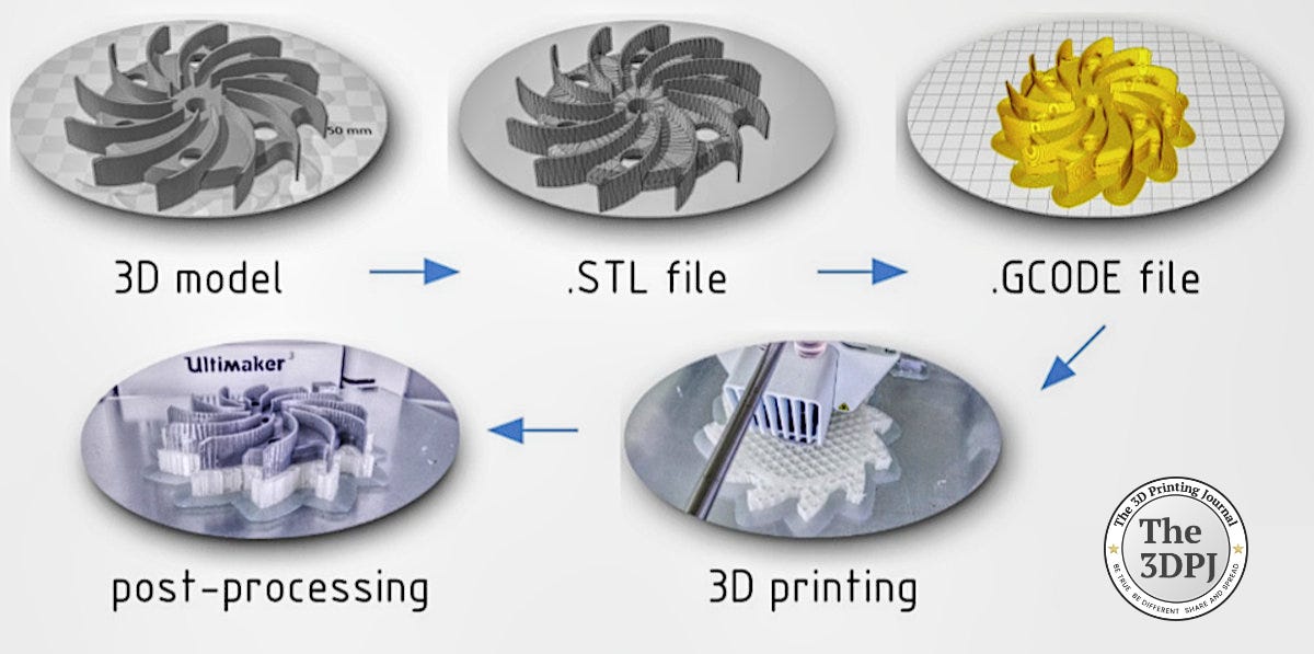
What is STL?
Some of you might already know — for others, it might not have seemed important. But here’s an explanation anyway.
STL models are surface representations of solids made up of triangles . The simplest shape described in this way is a quadrilateral, made of four triangles, each representing a face. A cube, for example, has rectangular sides, each split into two triangles. Even these simple shapes though could be represented by different numbers of triangles, because they can be subdivided and refined to tesselate the surfaces.


To correctly generate STL models, you need to understand how individual triangles behave. Each triangle has:
Three edges that connect at three nodes (vertices),
Vertices can only connect at nodes (i.e., they may share an edge, but a vertex from one triangle cannot lie on the edge of another),
Each triangle has a normal — a vector perpendicular to the surface, with a direction determined by the right-hand rule. This implies a “positive” and “negative” side to the surface. In STL, the positive side represents the outside of the model, and the negative side, the inside. This is crucial — even a single triangle with an inverted normal can ruin an entire print or cause issues with support generation
Then comes exporting a model to STL. Most CAD/CAM programs support this with conversion options that effectively define the triangle count by controlling a chord height. The lower the chord height, the closer the triangle approximates the original CAD surface creating a smoother curved surface appearance but the higher the triangle count and final part quality.


However, more triangles means larger and large file sizes — and with complex models, this can dramatically slow down slicers or printer software. In extreme cases, the file can crash the software or cause print errors due to computer memory issues.
Also, keep in mind that 3D printing resolution is controlled by layer height and tool width, so ultra-high triangle counts for precision depending on what is printed and where in the geometry
The conversion step can be problematic and is black boxed, even for experienced CAD users. Proper model preparation is essential — you can’t print directly from a 2D drawing. On top of differences in how STL export is handled across software, there can also be issues in the geometry itself.
Errors can arise even in simple models — for example, overlapping triangles after conversion. In more complex cases, entire sections might duplicate, detach from the rest of the model, or have incorrect triangle normals.
That’s why every STL file must be checked and often repaired before printing. This can be done in various 3D printing software tools.
Complicated, right?
Which brings us back to the initial thesis: industrial 3D printing should operate in a CAD → AM software workflow, without exporting to STL or another mesh based format such as 3MF which only fixes some of the inherent issues.
This isn’t a new concept — such solutions appeared as early as 2016 in GrabCAD (by Stratasys), and also in CURA plugins from Ultimaker. In metal AM, a similar solution is now offered by Dyndrite.
Why native CAD is better than STL for 3D printing?
Using native CAD files instead of STL meshes in additive manufacturing offers significant advantages across the entire workflow. Native CAD preserves parametric features, constraints, and design history, enabling intelligent modifications rather than basic geometry edits.
This allows for fast and flexible design changes, without the need to remodel from scratch, as is often required with static STL files.
Native CAD also maintains precise geometry without triangulation or approximation, avoiding the resolution limits and faceting errors common in STL exports. As a result, curved surfaces stay true to design and surface quality improves dramatically.
Moreover, native CAD files are much smaller in size, especially for complex parts, because they store parametric data instead of millions of triangles. They also support design automation through scripts or configuration tables, enabling scalable part variation workflows.
They can leverage feature-based printing, targeting specific geometries such as holes or overhangs directly from CAD—a process that’s difficult and manual with STL.
CAD files also prevent manufacturing errors by avoiding common mesh issues like holes or inverted normals. Their embedded metadata—such as color, labels, and region IDs—enables automated build preparation, parameter assignment, and support strategies.
Advanced tools like Dyndrite LPBF Pro leverage native CAD metadata such as color, labels, and region IDs to enable a wide-variety of automations such as those listed above.
This codifies engineering knowledge, streamlines repeatability, and reduces human error across teams and production sites.
Atomic Layer from the Past:
05-04-2015: Technology Applied – the largest polish AM service provider was born.
News & Gossip:
Zortrax (which has been undergoing restructuring) announced that it has received a lawsuit from DFM sp. z o.o., demanding PLN 511,065.41 in unpaid rent (~120k EUR). Zortrax plans to respond, considers the claim unfounded, and notes that most of the amount is included in a restructuring agreement from March 2025.
The US Army is testing low-cost, 3D-printed drones in Poland that detect electromagnetic signals like Wi-Fi and radar. Developed by a unit in Germany, the drones cost just $2,000–$3,000 each. Though still in development, the project aims to enable rapid, decentralized drone production outside traditional defense channels.
Adidas has officially launched its fully 3D printed Climacool sneaker. Developed with Carbon’s DLS technology, the shoe offers enhanced breathability, comfort, and performance. Priced at $140–$168, it features a seamless lattice structure and marks a major step in Adidas’ use of 3D printing in footwear.
I think the middle ground here is the STEP format. CAD software and slicing software are two different worlds, and it is nearly impossible to see a complete package that excels at both. Slicing is always a complex subject that still leaves room for improvement on the path to getting the best print results possible with the least effort for the printer operator and minimized material loss due to failed prints. On the other hand there are many CAD solutions that are great for designing (and maybe traditional manufacturing methods), but they offer only basic slicing features when it comes to additive manufacturing. So for any designer, be it industrial, art or home use; use one program for designing and/or simulation, and a dedicated slicing program to print the objects. So far STEP is the only solution that translates the object with its complete geometry between those environments, and gives the option to make proper modifications. If there is a better solution, I am ready to be educated.
Are CAM formats universal enough for slicers to be able to work with all of them?
I always saw stl as sort of the pdf of 3d printing....